Basic Examples
In this chapter, you will explore the capabilities of the kit. We will implement three small examples that will get you started with the basics.
You will learn
-
How to use the BL!XT dev kit API
-
How to control the current flow by enabling/disabling the current path
-
How to measure the current flow
-
How to configure a custom tripping threshold in software
-
How to use the zero cross detection
| In the following examples we will use a light bulb attached to a 230V AC outlet. Please make sure you unplug it from the mains if you need to touch the dev kit for anything else than uploading via the USB cable. Proceed with caution. |
On / Off
In the first example, you will learn how to control a current flow with the BL!XT hardware.
We will start with a simple switch that alternates between on and off and stays a second in each state.
Create a new project in PlatformIO and call it for example BCB_ON_OFF.
Remember to update platform.ini with your serial port settings.
Then copy the following program code into the projects main.cpp.
Hardware Setup
| Do not connect the power cable to any outlet before it is correctly wired to the dev kit. |
Connect the cable with power outlet as shown in this picture to the dev kit.
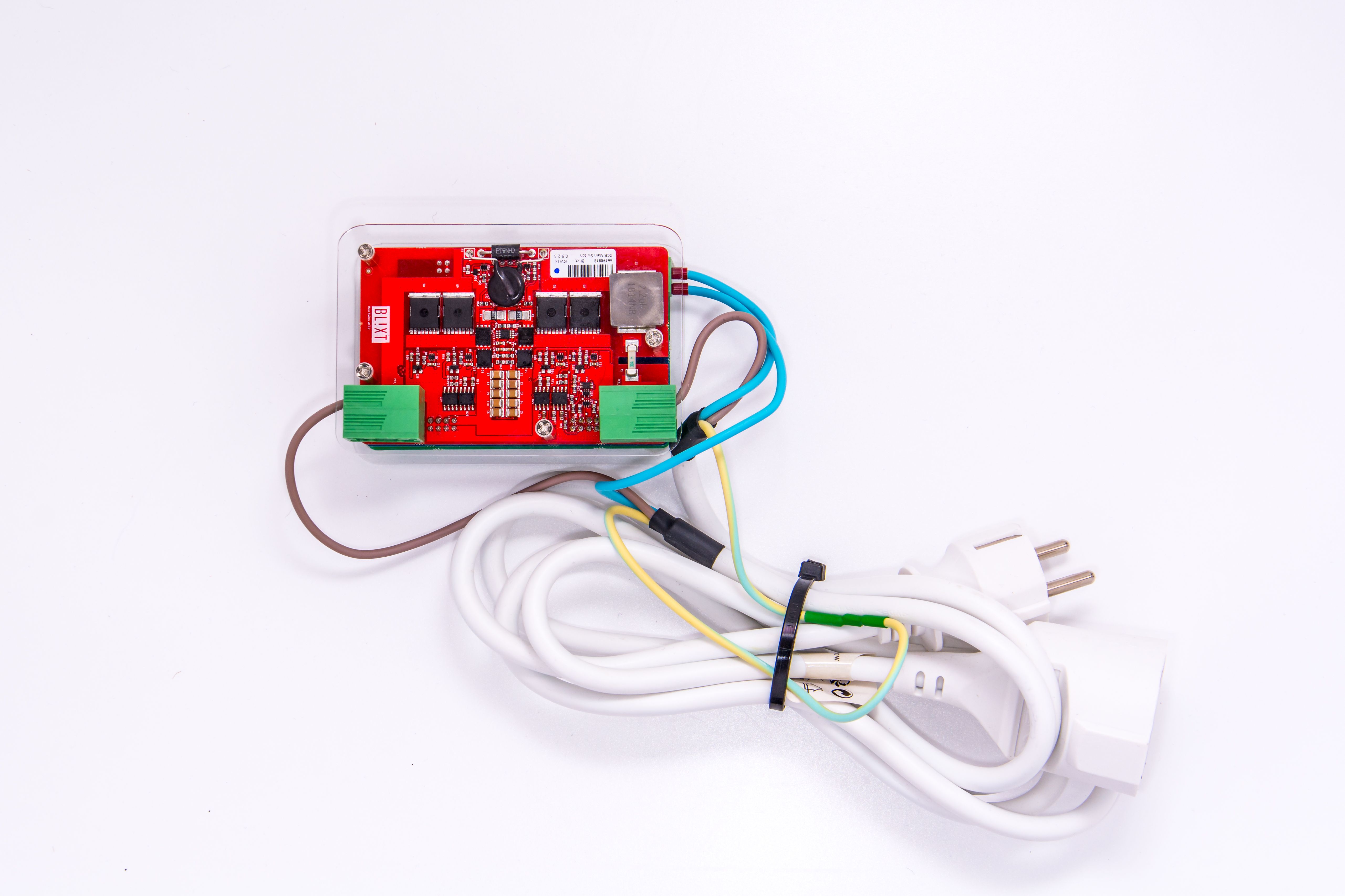
Connect the cable with the light socket to the power outlet of the cable. Finally, connect the USB to the dev kit and your computer.
Now you can connect the power cable to a wall outlet!
| Always make sure all power to the dev kit is turned off before touching the dev kit! |
Measuring Current and Voltage
In this example, you will learn how to measure the current and the voltage and print them out on the serial console. We will extend the On / Off example so that it will also measure the current drawn by the load.
Hardware Setup
Use the same setup as in the On/Off example.
Software
Create a new project in PlatformIO and call it BCB_MEASURING.
Remember to update platform.ini with your serial port settings.
Then copy the following program code into the projects main.cpp.
#include <Arduino.h>
#include <BCB.h>

void setup() {
  Serial.begin(115200);
  BCB::init();
}


void loop() {
  BCB::ledOn();
  BCB::on();
  Serial.printf("%d,%d\n",BCB::getCurrent(),BCB::getVoltage()); (1)
  delay(1000);
  BCB::off();
  BCB::ledOff();
  delay(1000);
}| 1 | Measure the currently drawn current and voltage and write the value on the serial port |
Software Programmed Threshold
We will extend the [measuring] example to handle a custom current threshold.
Hardware Setup
Use the same setup as in the On/Off example.
Software
Create a new project in PlatformIO and call it BCB_SW_THRES.
Remember to update platform.ini with your serial port settings.
Then copy the following program code into the projects main.cpp.
The code contains a number of delay() calls so that you can follow what is going on.
#include <Arduino.h>
#include <BCB.h>


void setup() {
  Serial.begin(115200);
  BCB::init();
  for (int i = 5; i != 0; --i) (1)
  {
    Serial.printf("Starting in %d\n",i);
    delay(1000);
  }
  BCB::on();
}


void loop() {
  static uint32_t SW_LIMIT = 10; // milli Amp (2)
  static const uint32_t STEP = 10; // milli Amp (3)
  bool isOn = BCB::isOn(); (4)
  auto current = BCB::getCurrent();

  uint32_t current_drawn = (uint32_t)abs(current); (5)

  if (isOn && (SW_LIMIT < current_drawn)) (6)
  {
    BCB::off();
    BCB::ledOff();
    Serial.printf("Too much current %" PRId32 "\n", current_drawn);
    delay(500);
  }
  else if (!isOn) (7)
  {
    SW_LIMIT += STEP;
    BCB::on();
    BCB::ledOn();
    Serial.printf("New SW Limit %" PRIu32 "\n",SW_LIMIT);
    delay(500);
  }
  else (8)
  {
    Serial.printf("Current %" PRIu32 "\n", current_drawn);
    delay(500);
  }

}| 1 | We give ourselves some time before the start so we can see properly |
| 2 | Current Limit |
| 3 | Step size |
| 4 | Check if CB is on |
| 5 | Current can be negative if measured during negative AC cycle, so make it absolute |
| 6 | If it is on and the current exceeds the limit turn it off |
| 7 | If it is not on, turn it on and increase the limit |
| 8 | If it is on and no current threshold overstepping, print the drawn current |
Putting it all together
Before uploading the firmware make sure the lamp is enabled. Once the firmware is uploaded, you should see the light bulb being turned on and off, while the length of the ON intervals keeps increasing until the light bulb is permanently on. If you follow the output on the serial console you can see how the program keeps on stepwise increasing the software limit.
Count Zero Crossings
In this example, you will learn how to use the build in zero cross detection.
Hardware Setup
Use the same setup as in the On/Off example.
Software
Create a new project in PlatformIO and call it BCB_COUNT_ZERO.
Remember to update the platform.io with your serial port settings.
Then copy the following program code into the projects main.cpp.
#include <Arduino.h>
#include <BCB.h>
volatile bool crossed = false; (1)
volatile unsigned long c_time = 0; (2)

void zero_counter() (3)
{
    crossed = true;
    c_time = millis();
}

void setup() {
  Serial.begin(115200);
  BCB::setCallbackZD(zero_counter); (4)
  BCB::init();
  BCB::on();
  BCB::ledOn();
}

void loop() {
    if (crossed)
    {
        crossed = false;
        auto lc(c_time);
        Serial.printf("Crossed at %ld!\n",lc);
    }
}
There are four new steps in this example:
| 1 | Status variable is set by the interrupt routine. Notice the volatile keyword. |
| 2 | Stores crossing time in milliseconds. |
| 3 | Definition of a callback function that sets the flag and stores the time. |
| 4 | Register the function as interrupt callback for zero crossing detection. |
Putting it all together
After compiling and uploading the program, open the serial monitor. If you have turned on the light bulb switch, you will see a lot of 'Crossed at <time>!' been printed. Turn the light bulb off and the text flow will stop.
As an experiment change <4> to off(), reupload and turn the light bulb switch on. What happens?
Software Controlled Threshold with Zero Crossing Turn On
In this example, you will combine the zero cross detection with the software programmable current threshold. We will reuse the threshold example and extend it so that the device only starts at the next zero crossing.
| The hardware can also to be configured to turn on at a zero-crossing by switching the zero-cross starter switch on. |
Hardware Setup
Use the same setup as in the On/Off example.
Software
Create a new project in PlatformIO and call it BCB_SWT_0X.
Remember to update platform.ini with your serial port settings.
Then copy the following program code into the projects main.cpp.
#include <Arduino.h>
#include <BCB.h>

volatile bool crossed = false;

void zero_counter()
{
    crossed = true;
}

void setup() {
  Serial.begin(115200);
  BCB::setCallbackZD(zero_counter);
  BCB::init();
  for (int i = 5; i != 0; --i)
  {
    Serial.printf("Starting in %d\n",i);
    delay(1000);
  }
  BCB::on();
}


void loop() {
  static uint32_t SW_LIMIT = 10; // milli Amp
  static const uint32_t STEP = 10; // milli Amp
  bool isOn = BCB::isOn();
  auto current = BCB::getCurrent();

  uint32_t current_drawn = (uint32_t)abs(current);

  if (isOn && (SW_LIMIT < current_drawn))
  {
    BCB::off();
    BCB::ledOff();
    Serial.printf("Too much current %" PRId32 "\n", current_drawn);
  }
  else if (!isOn)
  {
    SW_LIMIT += STEP;
    crossed = false; (1)
    while(!crossed); (2)
    BCB::on(); (3)
    BCB::ledOn();
    while(!BCB::isOn()); (4)
    Serial.printf("New SW Limit %" PRIu32 "\n",SW_LIMIT);
  }
  else
  {
    Serial.printf("Current %" PRIu32 "\n", current_drawn);
  }
  delay(100); (5)
}
The program is primarily a combination of the examples 'Count Zero Crossings' and 'Software Programmed Threshold'. The important parts to note are
| 1 | Reset the zero crossed flag. |
| 2 | Busy loop to wait for the next crossing. |
| 3 | Turn the current on. |
| 4 | Busy loop to wait for the kit to be actually on. |
| 5 | A delay to allow to follow the events. |