Advanced Examples
In this section you will explore the more advanced functionality of the hardware based. You should work through the basic examples first before starting with this section as their concepts will be used here.
Modulating Control
In this example you will combine zero crossing detection with the simple on / off functionality to build a modulating control system.
Hardware Setup
Use the same setup as in the On/Off example.
Software
#include <Arduino.h>
#include <BCB.h>

volatile uint32_t zd_ctr = 0;
volatile uint32_t msecs  = 0;

void on_zero_detect() {
  zd_ctr = (zd_ctr + 1) % 4;
  msecs = millis();

  switch (zd_ctr) { (1)
    case 0:
      BCB::on();
      break;

    case 2:
      BCB::off();
      break;

    default:
      break;
  }
}

void setup() {
  Serial.begin(115200);
  BCB::init();
  BCB::setCallbackZD(on_zero_detect);
  BCB::on();
}

void loop() {
  volatile uint32_t c = zd_ctr;
  volatile uint32_t t = msecs;

  Serial.printf("%" PRIu32 ",%" PRIu32 "\n", t, c);
}| 1 | Action based upon the counter |
Not much is happening in this code. The main logic sits in the callback function during zero crossing. Based upon the counter it will enable or disable the current flow. This code will enable every other full sine period. The full sine is important as it would otherwise create disturbances in the grid.
Putting it all together
| If you want to build a light dimmer, you need to add a filter to the setup. The Dev Kit is only using the light bulb as a simple visual example for this use case. A more realistic load could be a water kettle for example. |
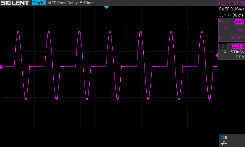
When uploading the code to the dev kit, you will start to see the light bulb flicker. While monitoring the current to the light bulb in an oscilloscope you should see a similar picture to the one below.